
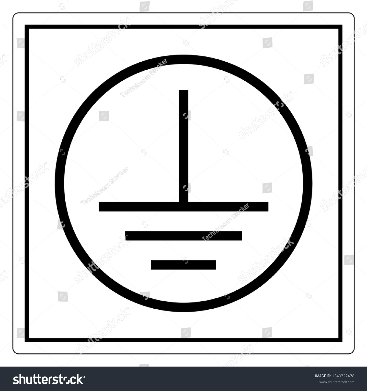
Vertical Sign ESD / Static Ground Wire
The ground symbol is typically used on the wiring diagram to show the ground point, which may be a bolt on the chassis or a specific wire. Ground points are usually located at the negative terminal of the battery and often used to ground the voltage regulator. It is also commonly used to ground switches and relays.

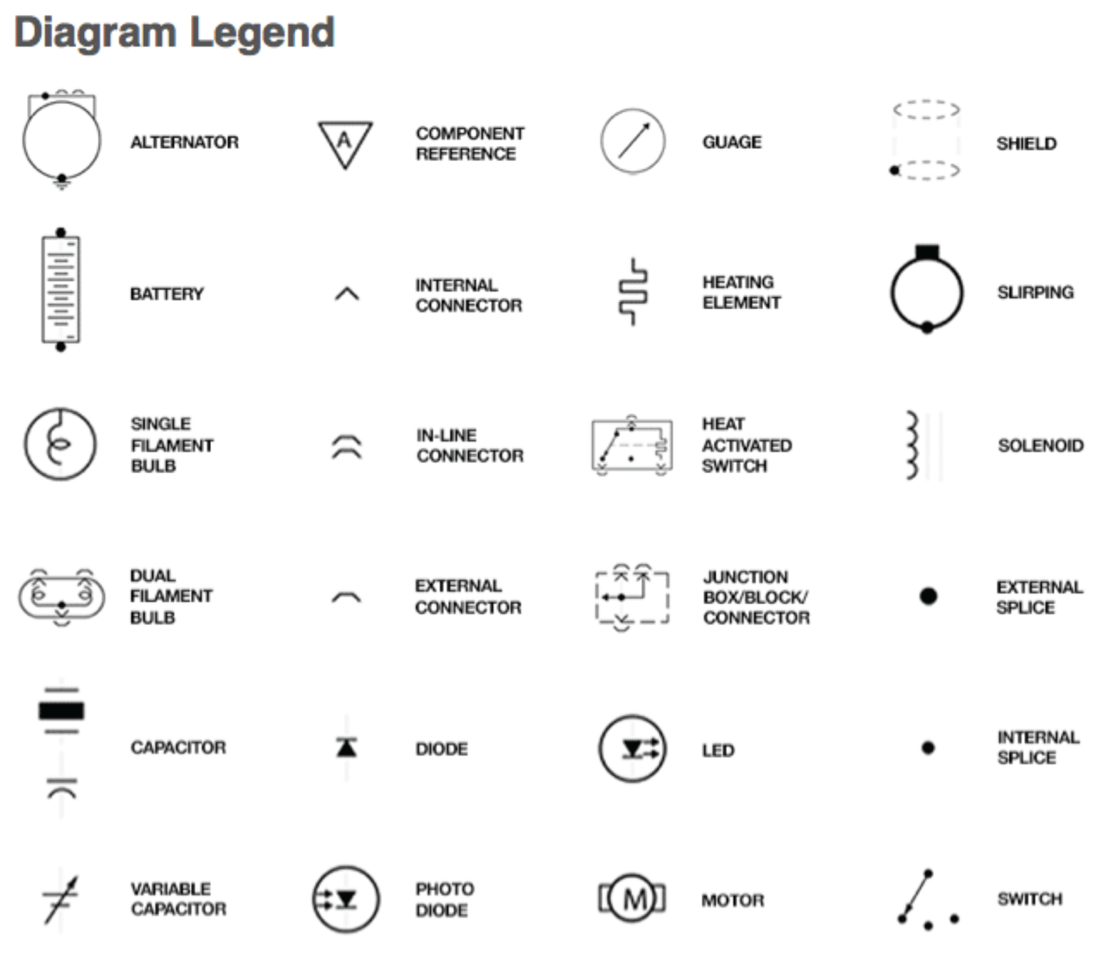
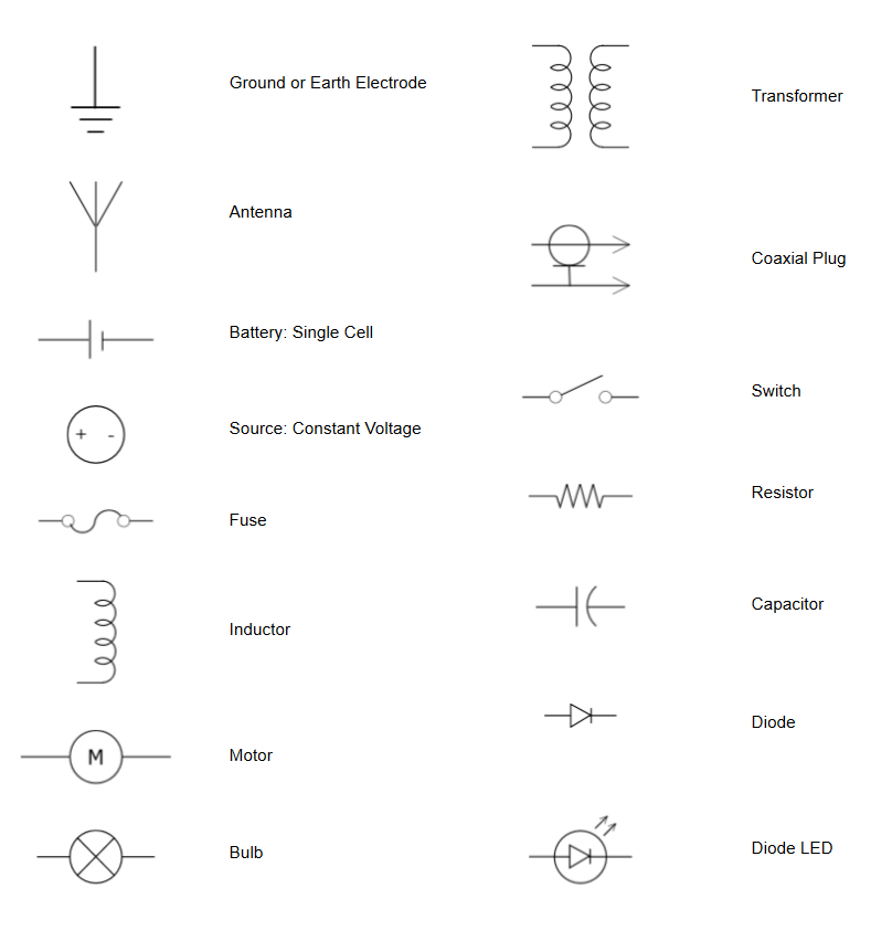
Electrical Wiring Symbols, Meanings and Drawings
Building wiring installations Electrical power distribution systems are often connected to earth ground to limit the voltage that can appear on distribution circuits.
Chassis Ground Electronic Symbol Circuit Diagram Png Clipart Angle
Definition of Terms. Earth ground: The point where the grounding system will run to the planet. This can be achieved with a copper rod hammered into the soil or a connection to a water pipe (ideally copper). Places that rely on good earth (telephone exchanges, radio stations, power stations) often bury large pieces of copper mesh or copper plates. In the case of transmitters, radials can be.

Identifying Wires on Your Old Switch Brilliant Support
The Ground Symbol So instead of drawing lines to all the places that should be connected to minus, you instead place the ground symbol there. This makes the circuit diagram much cleaner when there are a lot of connections to minus. An example circuit using ground symbols Flow of Current When the Ground Symbol is Shown

Ground Wire Explained YouTube Free Design Software, Grounding Rod
Graphical Symbol Notice that we've used an electrical symbol for Earth Ground. This symbol is probably the most misused in electrical schematics. The symbols used to indicate ground terminals are found in the International Electrotechnical Commission document IEC 60417 Graphical Symbols for Use on Equipment.
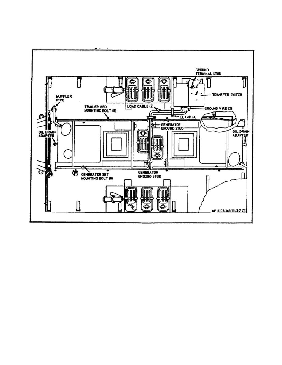
Figure 42. Ground Wire Location
Electronics ground symbols as defined in IEC 60417.. In 3-wire AC systems (hot, neutral, and ground wires), or in 3-wire DC systems (DC+, DC common, and ground wires) the chassis ground is normally connected to earth ground at the point where power comes into the plug in the system. A part of the system may also be connected to PCB chassis.
Label That Indicates Electrical Ground Wire Stock Illustration
18 I've been trained to use the word ground and the ground symbol to refer to the earth, the dirt on which we stand. Circuit common is considered to be a separate concept, with the symbol . My understanding is that "ground" means that the node can and should be tied to the earth.
Bestly Wiring Diagram Ground Symbol
Figure 1: There are three different electrical symbols for ground, indicating context within a schematic. Source: Wikipedia.. Grounding adds a third wire (a ground wire) to provide a path for current that is unable to complete the circuit. An exposed conductor wire, for instance, can create a situation where the current could flow through a.
Automotive Wiring Diagrams Symbols
The use of grounding symbols does not always strictly adhere to industry standards; it can be difficult to understand which ones are used and in what context. Most of the time the ground symbol you are most familiar with, the 3 decreasing-length lines, is the one that is used in a generic sense to illustrate ground.

Best Electrical Grounding Illustrations, RoyaltyFree Vector Graphics
The three ground symbol types that are shown are: earth, chassis, and signal. Keep reading: Grounding Electrical Circuits: 5 Simple Techniques Neutral vs Ground Wire: Common Power Problems The myth called "ground" List of Symbols and Abbreviations in Electronics Advertisement
Electrical grounding symbol vector. Grounding icon isolated. Vector
OEM | ODM In microelectronic circuits, we default to the ground wire as the 0V voltage reference point. You may see many different ground symbols on the PCB, so here are the ground symbols you see. 1.Whether it is analog ground or signal ground, it is generally marked with the following symbol.

What is Ground Wire Used For? Performance Wire and Cable
31 Electrical Wiring Symbols, Meanings and Drawings by Santosh Das | Last Updated On December 15, 2023 Electrical Wiring Symbols, Meanings and Drawings of All Electrical Symbols and their Function. Here is List of All the Electrical Wiring Symbols, Meanings and Drawings for both Residential and Commercial. Basic Electrical Wiring Symbols
Electrical Symbols Try Our Electrical Symbol Software Free
Common ground symbol. Typically, this reference point is the base for all other voltage measurements within the circuit. However, not all voltage measurements are taken from this reference point. For instance, if you were to measure the voltage across the upper resistor in a resistive voltage divider, your reference point would not be ground.

Technics Ground Wire SFEL02801E Grounding earthing, Wire, Technical
Ground or earth in a mains ( AC power) electrical wiring system is a conductor that provides a low- impedance path to the earth to prevent hazardous voltages from appearing on equipment (high voltage spikes). [citation needed]
Ground Wire ClipArt ETC
Electrical symbols & electronic circuit symbols of schematic diagram - resistor, capacitor, inductor, relay, switch, wire, ground, diode, LED, transistor, power supply, antenna, lamp, logic gates,.
Ground wire symbol Images, Stock Photos & Vectors Shutterstock
No. 5018 Noiseless (clean) earth (ground): To identify a noiseless (clean) earth (ground) terminal, e.g. of a specially designed earthing (grounding) system to avoid causing malfunction of the equipment.